The forum is currently inactive due to too much AI spam.
GA-Z77-DS3H / EVC2

Quote from 0x54_0x6F_0x6D on 2020-06-20, 18:16Hi community,
i just got an EVC2 as a birthday present and now i want to use it to overclock my old i5 3570K on a Gigabyte GA-Z77-DS3H.
The problem with this MB is, that it has no vCore setting in BIOS whatsoever. So i dont know if it is even possible to set the voltage with EVC2.
Currently i'm struggling with finding the voltage controller on that board and the right spot to solder the pins on to connect the I2C1 header to the MB.
I would really appreciate it, if someone could help me with this. If you need pictures of the MB i can post them.
Cheers,
Tom
Hi community,
i just got an EVC2 as a birthday present and now i want to use it to overclock my old i5 3570K on a Gigabyte GA-Z77-DS3H.
The problem with this MB is, that it has no vCore setting in BIOS whatsoever. So i dont know if it is even possible to set the voltage with EVC2.
Currently i'm struggling with finding the voltage controller on that board and the right spot to solder the pins on to connect the I2C1 header to the MB.
I would really appreciate it, if someone could help me with this. If you need pictures of the MB i can post them.
Cheers,
Tom
Quote from 0x54_0x6F_0x6D on 2020-06-20, 19:56I think I found the voltage controller but I still have no idea how to connect to it. And it is also not listed in the I2C_DEVICES folder from the EVC2_1.0.1.2d ZIP I downloaded.
I made a picture of what I think is the voltage controller and I also found a PDF with pinout. (see attachments).
I think I found the voltage controller but I still have no idea how to connect to it. And it is also not listed in the I2C_DEVICES folder from the EVC2_1.0.1.2d ZIP I downloaded.
I made a picture of what I think is the voltage controller and I also found a PDF with pinout. (see attachments).
Uploaded files:
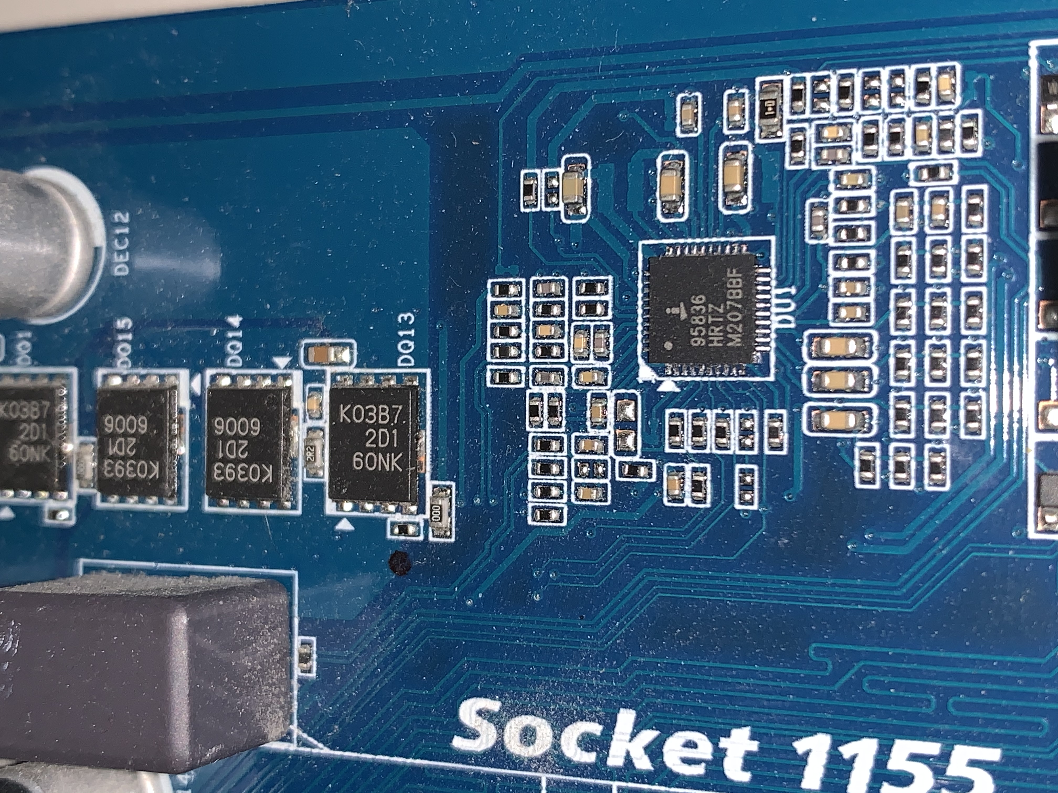

Quote from elmor on 2020-06-20, 20:14I think you've found the correct chip. You're right that there's no existing profile for this specific controller right now. From what I can tell, the controller supports only the Intel SVID interface and not I2C/SMBus. That means the EVC2 can't talk to it using those headers.
But you can try to use the VMOD header by connecting VIN to your output voltage and SRC to the controller FB pin as shown in the attached picture.
edit: Realised it supports only SVID, not I2C
edit2: Wrong picture uploaded
I think you've found the correct chip. You're right that there's no existing profile for this specific controller right now. From what I can tell, the controller supports only the Intel SVID interface and not I2C/SMBus. That means the EVC2 can't talk to it using those headers.
But you can try to use the VMOD header by connecting VIN to your output voltage and SRC to the controller FB pin as shown in the attached picture.
edit: Realised it supports only SVID, not I2C
edit2: Wrong picture uploaded
Uploaded files:
Quote from 0x54_0x6F_0x6D on 2020-06-20, 21:17Thanks for the fast reply elmor! 🙂
I will try out your recommendation.
Edit: Because I am a complete newbie regarding voltage mods, it is not clear for me what you mean by that:
„connecting VIN to your output voltage“
Where do I get the output voltage? Is it also a pin of the controller?
Thanks for the fast reply elmor! 🙂
I will try out your recommendation.
Edit: Because I am a complete newbie regarding voltage mods, it is not clear for me what you mean by that:
„connecting VIN to your output voltage“
Where do I get the output voltage? Is it also a pin of the controller?
Quote from elmor on 2020-06-20, 22:19Quote from 0x54_0x6F_0x6D on 2020-06-20, 21:17Thanks for the fast reply elmor! 🙂
I will try out your recommendation.
Edit: Because I am a complete newbie regarding voltage mods, it is not clear for me what you mean by that:
„connecting VIN to your output voltage“
Where do I get the output voltage? Is it also a pin of the controller?
No worries. That would be anywhere you can measure Vcore, for example one of the output capacitors. The small colored indicator is for the negative lead which should be connected to ground (GND). The other side is the positive lead and should be connected to the output voltage. Because this controller has 2 outputs, you may want to double check that it's really Vcore your measuring where you decide to connect it to. Comparing the voltage with BIOS or CPU-Z should be enough. I think the capacitors I've indicated in the attachment are very likely to be for Vcore.
Quote from 0x54_0x6F_0x6D on 2020-06-20, 21:17Thanks for the fast reply elmor! 🙂
I will try out your recommendation.
Edit: Because I am a complete newbie regarding voltage mods, it is not clear for me what you mean by that:
„connecting VIN to your output voltage“
Where do I get the output voltage? Is it also a pin of the controller?
No worries. That would be anywhere you can measure Vcore, for example one of the output capacitors. The small colored indicator is for the negative lead which should be connected to ground (GND). The other side is the positive lead and should be connected to the output voltage. Because this controller has 2 outputs, you may want to double check that it's really Vcore your measuring where you decide to connect it to. Comparing the voltage with BIOS or CPU-Z should be enough. I think the capacitors I've indicated in the attachment are very likely to be for Vcore.
Uploaded files:
Quote from 0x54_0x6F_0x6D on 2020-08-21, 20:02Hi,
after a first try i was not able to get the correct voltage read out and struggled with sothering on the cable to the FB pin.
After not touching the „project“ for a while I tried it again and managed to find a point to measure Vcore and there was also a point at the backside of the MB which is connected to FB and after sothering on the cable for SRC there it was possible to control the CPU core voltage. 🙂
@elmor thanks again for your help 😀
Hi,
after a first try i was not able to get the correct voltage read out and struggled with sothering on the cable to the FB pin.
After not touching the „project“ for a while I tried it again and managed to find a point to measure Vcore and there was also a point at the backside of the MB which is connected to FB and after sothering on the cable for SRC there it was possible to control the CPU core voltage. 🙂
@elmor thanks again for your help 😀
Quote from elmor on 2020-08-22, 22:38Quote from 0x54_0x6F_0x6D on 2020-08-21, 20:02Hi,
after a first try i was not able to get the correct voltage read out and struggled with sothering on the cable to the FB pin.
After not touching the „project“ for a while I tried it again and managed to find a point to measure Vcore and there was also a point at the backside of the MB which is connected to FB and after sothering on the cable for SRC there it was possible to control the CPU core voltage. 🙂
@elmor thanks again for your help 😀
Cool, glad you got it working 🙂
Quote from 0x54_0x6F_0x6D on 2020-08-21, 20:02Hi,
after a first try i was not able to get the correct voltage read out and struggled with sothering on the cable to the FB pin.
After not touching the „project“ for a while I tried it again and managed to find a point to measure Vcore and there was also a point at the backside of the MB which is connected to FB and after sothering on the cable for SRC there it was possible to control the CPU core voltage. 🙂
@elmor thanks again for your help 😀
Cool, glad you got it working 🙂
