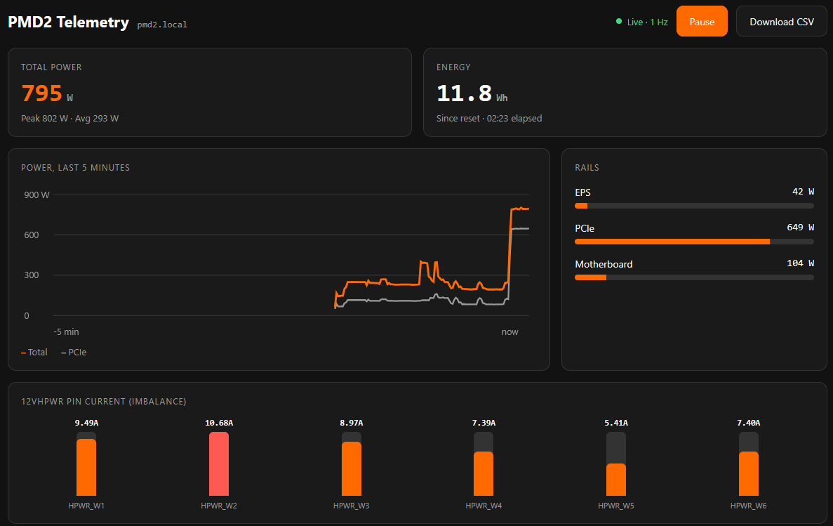
A minimal ESP32C6 sketch demonstrating the PMD2X’s SPI command protocol & reference code for anyone building their own integration.
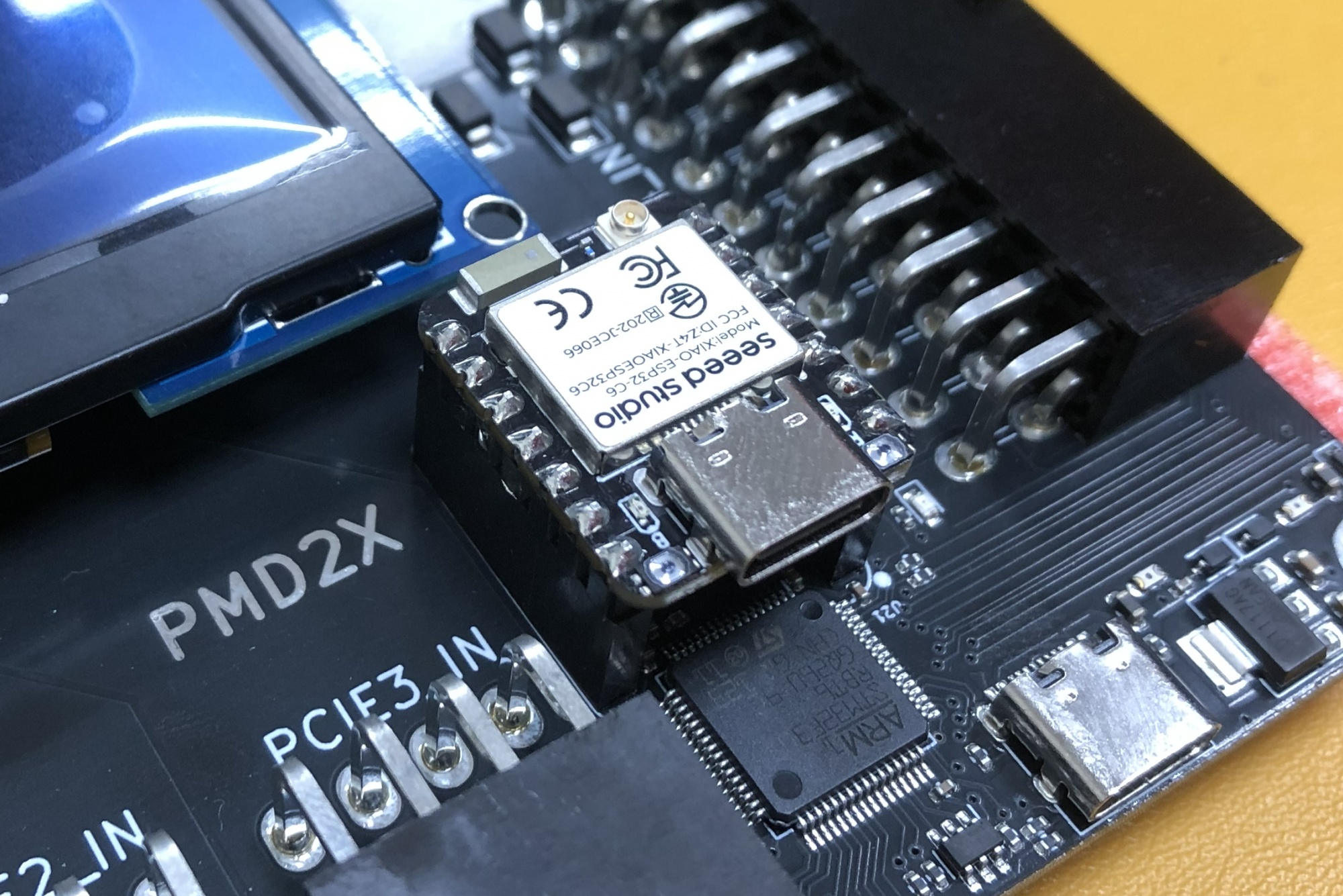
The ElmorLabs PMD2X exposes live voltage, current, and power readings across your CPU (EPS), GPU (PCIe and 12VHPWR), and motherboard (ATX24) rails over a simple SPI interface. If you want to read that data from your own project (a custom dashboard, a logging tool, an automation script) you need to know how to speak that protocol.
The SPI Command Tester is exactly that: a small, readable ESP32C6 sketch that implements the full command set and gives you a command line to try it out.
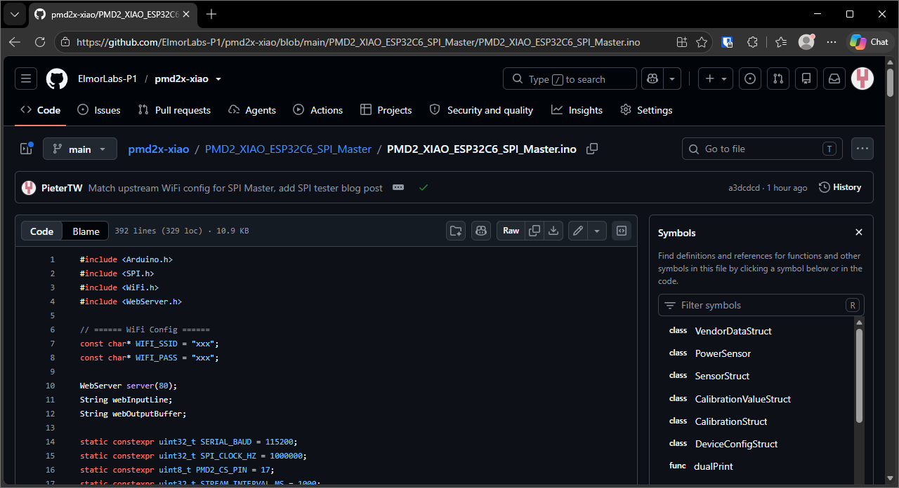
It’s available for download from our public GitHub repo at PMD2_XIAO_ESP32C6_SPI_Master.ino. It needs your WiFi SSID and password compiled in for its optional web console, so there’s no single prebuilt binary that could work for everyone out of the box. You need to build it yourself with your own credentials.
The hardware: Seeed Studio XIAO ESP32C6
This sketch runs on the Seeed Studio XIAO ESP32C6, a thumbnail-sized development board built around Espressif’s ESP32C6 (WiFi 6, Bluetooth LE, and 802.15.4) included with every ElmorLabs PMD2X.
The PMD2X’s onboard header follows Seeed’s XIAO form factor, so it isn’t locked to the ESP32C6 specifically. Any board in the XIAO ecosystem that fits that same header works, including variants built around other microcontrollers (RP2040, SAMD21, nRF52840, and others).
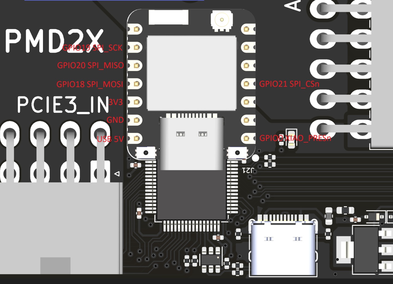
The SPI wiring and protocol in this sketch stay the same regardless of which XIAO module you plug in; only the Arduino board package and pin mapping names may change.
What it’s for
- A working protocol reference: every PMD2X SPI command (
welcome,vendor,uid,device,config,sensor,reset) implemented in plain, readable Arduino code: how to assert chip select, send a command byte, and clock out the response. - Two ways to try it: a USB serial console, or a bare HTML page served from the ESP32C6 itself, with a single text box and a scrolling log.
If you’re starting a project that talks to the PMD2X over SPI, this is a good first thing to flash and read through before writing your own code against the protocol.
Building and flashing it with the Arduino IDE
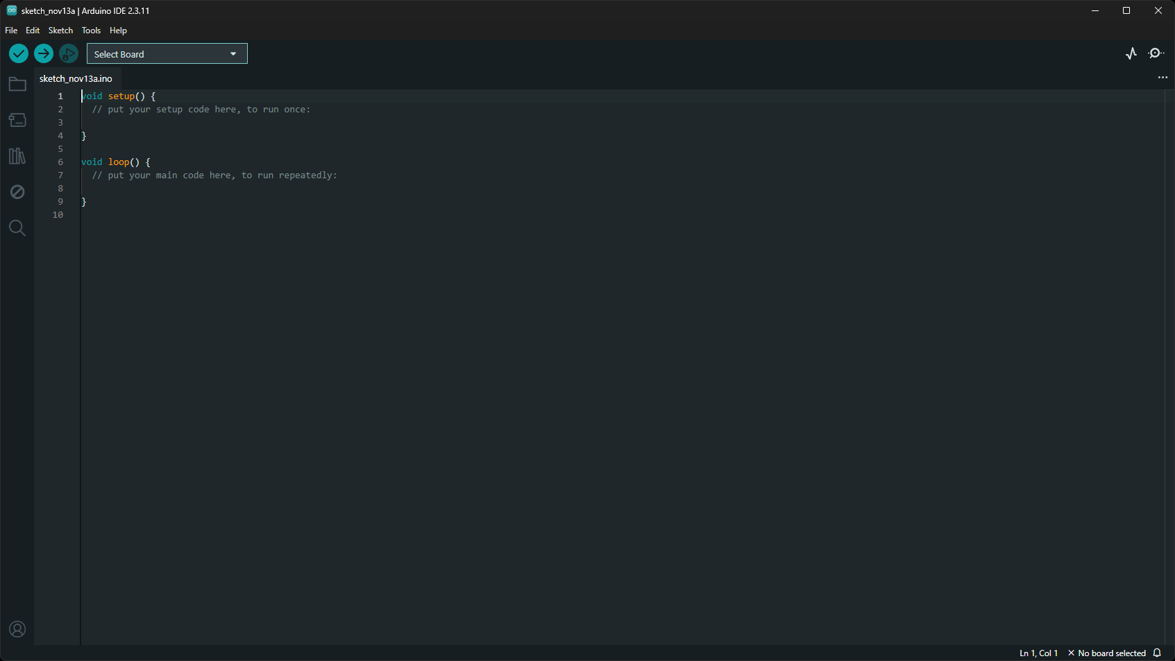
Connect the Xiao ESP32C6 module to your PC with. Then, install the Arduino IDE: https://www.arduino.cc/.
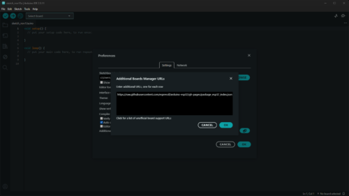
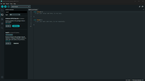
Install the ESP32 board package:
- File → Preferences → Additional Boards Manager URLs, add:
https://raw.githubusercontent.com/espressif/arduino-esp32/gh-pages/package_esp32_index.json - Tools → Board → Boards Manager, search “esp32”, install the Espressif package.
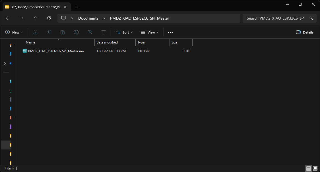
Get the sketch. Download PMD2_XIAO_ESP32C6_SPI_Master.ino into its own folder named PMD2_XIAO_ESP32C6_SPI_Master (Arduino requirement) and open it.
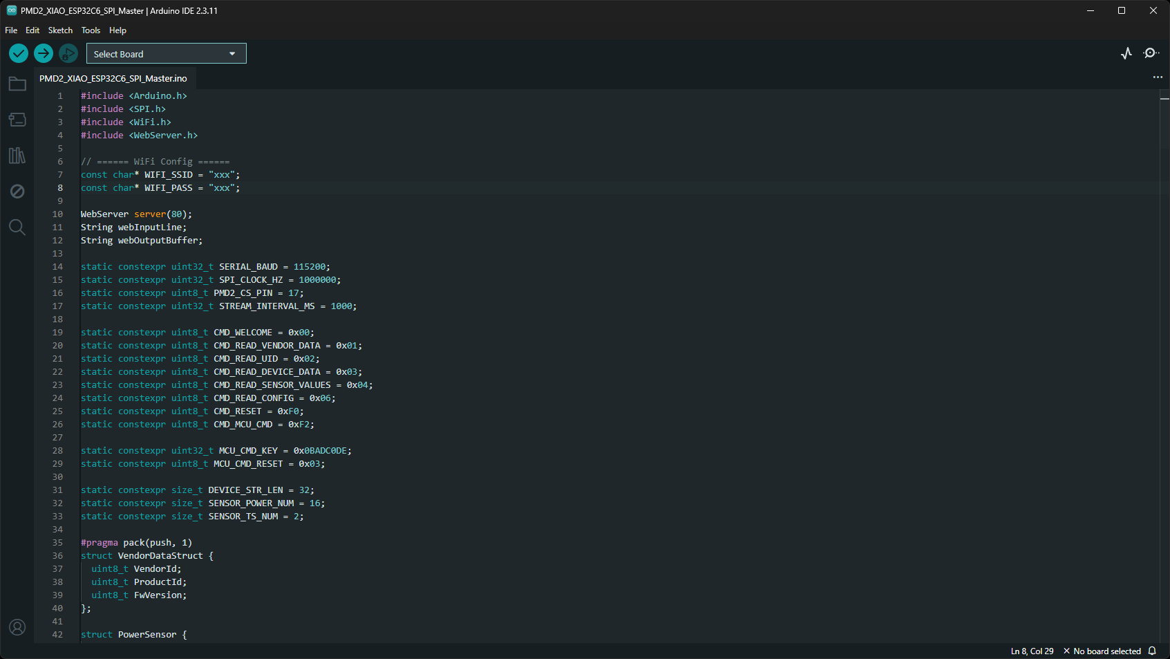
Add your WiFi credentials. This sketch connects to WiFi on boot (for its optional web console) and will sit there waiting if it can’t. Near the top of the file, edit these two lines with your network’s SSID and password:
const char* WIFI_SSID = "xxx";const char* WIFI_PASS = "xxx";
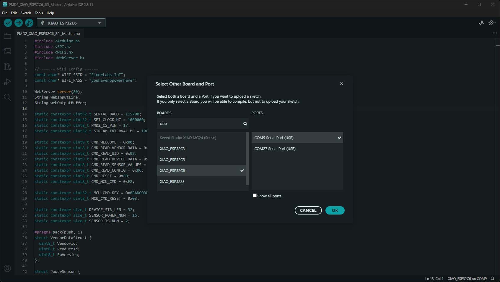
Pick the board and port: Tools → Board → esp32 → XIAO_ESP32C6, then Tools → Port and select the ESP32C6’s serial port.
Partition scheme: Tools → Partition Scheme, any default scheme works. This sketch is small and doesn’t need OTA space.
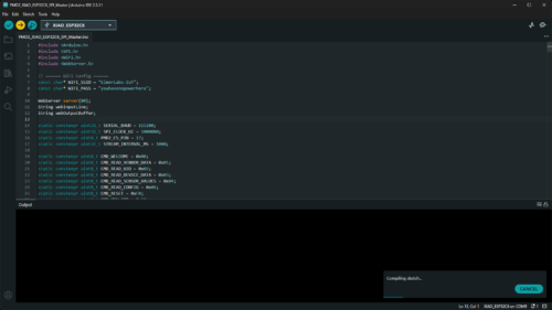
Upload. Click the arrow button. The IDE compiles and flashes over the selected port.
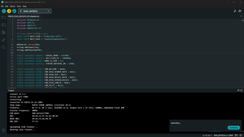
Open the Serial Monitor at 115200 baud. You’ll see the boot log and a command list, and you can type commands straight into the input box.
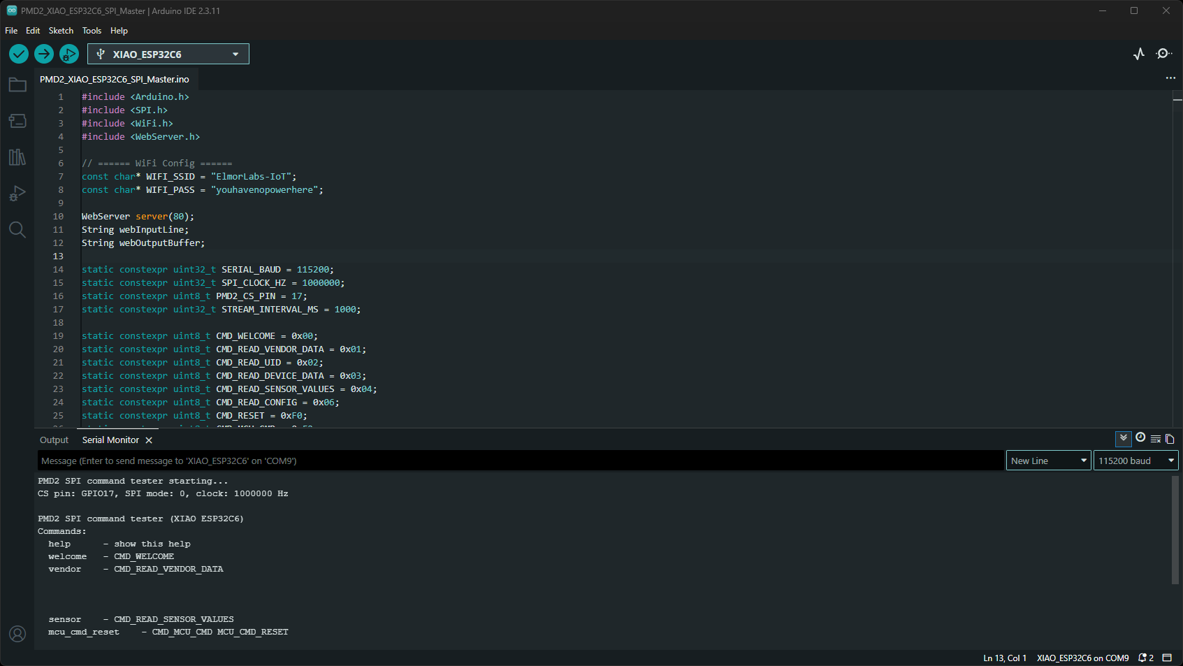
Trying it out
Once it’s running, type help into the Serial Monitor for the full command list. The one you’ll reach for most is sensor.
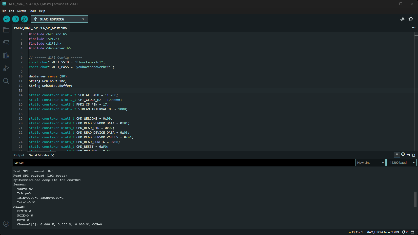
This prints the PMD2X’s full sensor frame: supply voltage, chip temperature, both 12VHPWR thermistors, total power, and every individual voltage/current/power channel. If the PMD2X is alive and the SPI link is healthy, you’ll see real numbers. If you see all zeros across the board (Vdd=0 mV, Total=0 W, every channel reading 0.000) that’s a strong signal the PMD2X’s SPI responder has gotten stuck, not that anything is wrong with the ESP32 side. A full power-cycle of the PMD2X (not just the ESP32) is the known fix for that today.
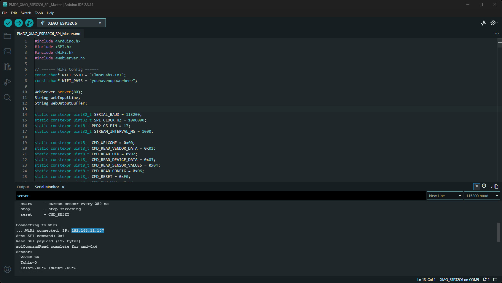
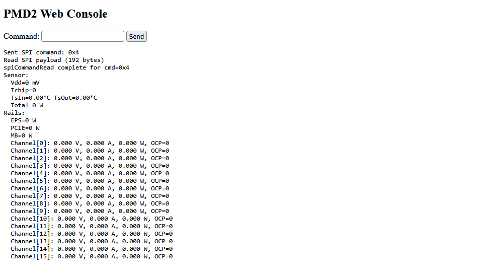
You can also reach the same console from a browser: once connected to WiFi, the sketch’s serial log prints an IP address. Simply open that in a browser for a minimal web page with a text box and a live-updating log, useful if you’d rather not tie up a USB serial connection.
Useful commands
| Command | What it does |
|---|---|
welcome | Reads the PMD2’s product name string. |
vendor | Vendor ID, product ID, and the PMD2X’s own firmware version. |
uid | The PMD2X MCU’s 12-byte hardware UID. |
device / config | Reads back the device configuration summary. |
sensor / once | A single full sensor reading. |
start / stop | Streams a sensor reading every 250 ms, handy for watching values change in real time. |
reset | Tells the PMD2X to reboot. |
Reading the code
Each command handler in the sketch follows the same shape: send a one-byte command over SPI with chip select held low, then clock out the expected response length. The structs it reads into (SensorStruct, DeviceConfigStruct, VendorDataStruct) mirror the PMD2’s wire format exactly, down to #pragma pack(push, 1) to avoid padding.
Start with cmdReadSensor() for the most useful example, then spiCommandRead() underneath it for the raw SPI mechanics every other command builds on.
What’s next
Once you’re comfortable with the protocol, the natural next step is building something on top of it. For example, a live-updating dashboard, a logging tool, your own automation.
One example of that is the XIAO Dashboard, a full wireless telemetry station built on this same SPI link: live charts, CSV export, a JSON API, and WiFi setup with no credentials compiled in. More on that in a future post.