Many like to tinker with their motherboard load-line settings to achieve better overclocking results. But how does this setting really work and how does the voltage output change with it? Check below to find out.
What is Load-Line?
The load-line setting, normally in mΩ (milliohms), determines how much the output voltage decreases when loaded. This is derived from Ohm’s Law U = R*I. The drop in output voltage is calculated as load-line * Iout (output current). For example a load-line of 1 mΩ and output current of 100 A, dU = 0.001 Ω * 100 A = 0.100 V. At 1.300 V set-point output voltage, when loaded with 100 A the output would really be 1.300 – 0.100 = 1.200 V. The primary reason for using a load-line in modern systems is to reduce voltage spikes (overshoot) when going from high to low output current and achieve a more predictable behavior.
What are Motherboard Load-Line Levels?
| Vendor | Option | Values (high to low) |
| ASRock | CPU Load-Line Calibration | Level 5 to Level 1 |
| ASUS | CPU Load-line Calibration | Level 1 to Level 8 |
| Gigabyte | CPU Vcore Loadline Calibration | Turbo, Extreme, Ultra Extreme |
| MSI | CPU Loadline Calibration Control | No OV, Mode 8 to Mode 1 |
Load-Line Levels or similar are profiles created by motherboard manufacturers to obfuscate and “simplify” different load-line values for users. Another reason for these profiles is because additional VRM (Voltage Regulator Module) settings may need to adjusted along with the load-line value to keep it operating within spec.
Test setup
- ROG Maximus XI Gene (BIOS 1005)
- Intel Core i9-9900K @ 4.7G 1.200V
- Siglent SDS1104X-E
- Test leads connected to CPU die-sense pins
Summary
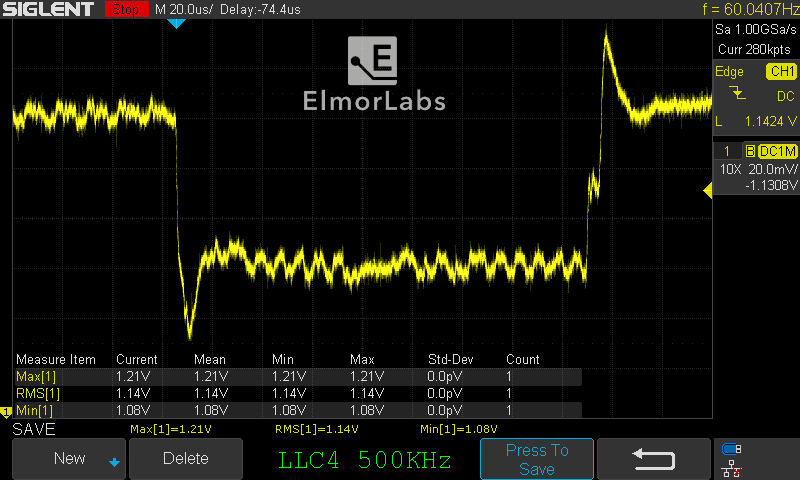
The captures below show the output voltage transient behavior when loaded with about 70 A for ~150 μs. The LLC1 capture illustrates ideal load-line behavior. As the load-line value decreases (higher level), the line flattens and the under/overshoot spikes at start and finish become more pronounced. The lowest voltage point at the beginning of the load transient does not improve much. In this case, using a Load-Line Level of above 3 seems questionable. The load voltage would increase meaning higher power consumption, but the worst case lowest voltage would stay the same. Additionally the over-shoot after load release increases. Increasing the VRM Switching Frequency from 500 KHz to 800 KHz shows very minor improvements.
Results
-

LLC1 500KHz -

LLC2 500KHz -
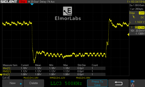
LLC3 500KHz -

LLC4 500KHz -

LLC5 500KHz -

LLC6 500KHz -

LLC7 500KHz -
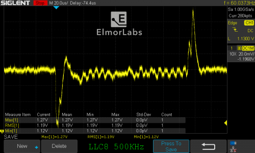
LLC8 500KHz


-

LLC1 800KHz -

LLC2 800KHz -

LLC3 800KHz -

LLC4 800KHz -

LLC5 800KHz -

LLC6 800KHz -

LLC7 800KHz -

LLC8 800KHz


